Write the content here to display this box.
MDriven Designer is a UML modeling tool that allows you to capture sufficient details to cover every aspect of a software system. It enables you to model the full specification of what you want to explain.
To make your experience smooth, we set the main tags mentioned in the video to the right bar menu of this mini-player. Choose an interesting subtitle on the list and immediately get to the exact theme navigation item place in the video. Now you can pick any topic to be instructed on without watching the whole video.
Installation of MDriven Designer
To outset the guidance we need:
- Go to the https://mdriven.net/designer site and open MDriven Designer by clicking "Run with ClickOnce".
- Note! For Chrome and Firefox, you may need a plugin to associate the .application extension with ClickOnce (plugin for Chrome / plugin or Firefox).
Click Once is the distribution technology from Microsoft. It updates every time there's a need; otherwise, the application stays in your internet cache, so that's a safe way to execute the application.
Once you’ve downloaded all the needed extensions and the browser is able to recognize them, you can safely launch the “MDriven Designer use the ClickOnce” link since you already signed in. It started with the “Default” or starting model.
Following up on the benefits of the MDriven Designer, you can define your model and do more, regarding your application. We argue that you can create complete software systems using nothing else but modeling with the help of the MDriven Designer. This may appear doubtful to you, so we encourage you to follow this guide to reach that conclusion yourself.
Setting a New Diagram
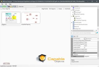
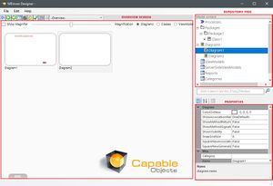
The overview screen, which is the first thing we see, shows what diagrams exist. In our case, as an example, we use only one diagram - "Diagram one". There is also a repository tree, where you can create and see the diagram structure. If we were to set up another diagram, by choosing '’Add Class diagram",' it would pop up on both the overview screen and repository tree as "Diagram2".
You can change your diagrams, for example changing "Diagram2" to “DiagramMyNewDiagram”. The things we point at in the tree usually have properties that might be set. (Object Inspector field of properties lies under the repository tree). We can also edit the “Diagram1” name on “DiagramMyFirstDiagram” straight from the “Name” properties menu in the Object Inspector. Some of these properties affect how the diagram should behave. There is no critical need to use them, but this is recommended for a better quality of control.
Add a Category
Chose the “Add a category” option in the repository tree area. The “New category” is supposed to have only one property name - we name it “Important” and another category as ”Less Important”. Once you have categories, you could set them on both diagrams as “Important”, for example.
To enter a whole diagram, double-click on it or press the “Switch Back Arrow” to return to the overview screen. Another way to move between the diagrams is by using the repository tree.
When you right-click the screen inside of the diagram, the options menu drops down, and we can “Add a class” - for instance, “Class1”, which will appear in the repository tree and overview screen section of “DiagramMyNewDiagram''.
Classes that are created live in a “Package”. You can have multiple packages, but it is not necessary to use multiple packages. Think of it as a way to section a software system or so-called namespace.
Following the logic, the diagram is just a representation of the class. Having created the “Class2” in the “DiagramMyNewDiagram'', we can always drag it from the repository tree to the “DiagramMyFirstDiagram” on the overview screen. That doesn't mean it disappears from the initial spot, as it’s just two different representations of the same classes that are in our complete model. In our repository for the model, you can add other things, including diagrams, to help you to get an overview or navigation, or to navigate between things. We can also include “DiagramMyNewDiagram” into “DiagramMyFirstDiagram”, which will be illustrated on the overview screen as a thumbnail picture of one diagram containing another.
If you are a newbie in UML or lack sufficient experience, you should follow our UML School: Class diagram.
Processes
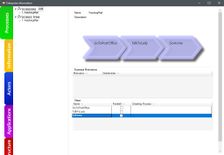
A process is just a workflow of the order in which you should do things. Double-click it on the repository tree and you will get the view of “Processes“ in the “Enterprise Window”.
We will name it “'Fetching Mail'” and create some steps involved in this process.
In such a manner, this is more like documentation of what you have learned in the domain that you're designing for. Once you have that, you could add a small “process diagram” to the screen and dress this up with more information as you model further.
Although we have reviewed two types of diagrams, there is one type that needs to create an attribute on the “Class1” to see and that is the important “StateMachine” diagram. Once we’ve added the StateMachine, we immediately jump into the new “StateMachine”, but, if we switch back, we should end up on the “DiagramMyFirstDiagram” field, having gotten the new attribute to the “Class1” called "State" that is actually a state attribute.
See: State Diagrams


